|
(1).
|
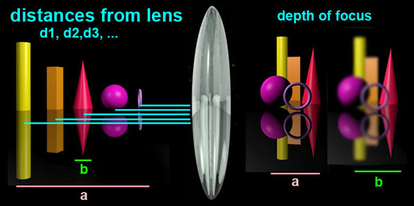
First the human eye ... the human eye (on average) can differentiate about 5 lines per mm at about 25cm from a viewing surface. It turns out that the eye also can comfortably view about a 60° range, and these two values are reached when an 8x10 inch print is viewed at about 10 inches (25 cm). The diagonal of the 8x10 held at about 10 inches produces a 60° field of view.
The 5 lines per mm corresponds to about 0.2 mm or optical resolution. Meaning the human eye cannot tell the difference between a 0.2 mm dot (spot) and a 0.2 mm ring with about 80% density. Now what this actually means is that an 8x10 inch negative that is contact printed will have a resolution limit at the 0.2 mm size. If a piece of smaller film (35mm or less) is used then you must first calculate the amount of enlargement before determining the actual limit. If the image is created from a 35mm negative, the enlargement to an 8x10 inch print is roughly 7x. Thus on the negative, the limit would be (0.2mm / 7 ) = 0.029 mm. This limiting value is known as the "circle of confusion" (COC), the point at which the eye cannot differentiate a sharp point from a blurry one. There are several "rules of thumb" for calculating this value. Zeiss formula, (d / 1730) or (d / 1500) where d is the diagonal measure of the film size (or ccd size). In this case for 35mm film the range is between 0.0248 - 0.0286, both of which are pretty close. For digital cameras here are some COC (circle of confusion values) (see this site for more)
|
|||||||||||||||||||||||||
|
|
 |
|||||||||||||||||||||||||
|
(2.)
|
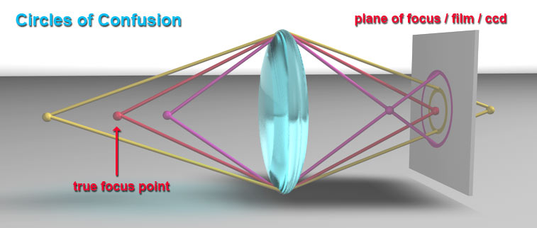
Lens physics ... the diagram above shows three points in the real world (left side) and they are being focused on to the plane on the right side. The true focal point of this lens is set to be the RED point, and it is perfectly focused on the plane. The point that is closer to the lens will be in sharp focus in front of the plane and is represented by the magenta point. The image will be out of focus and produce the large magenta circle on the plane.
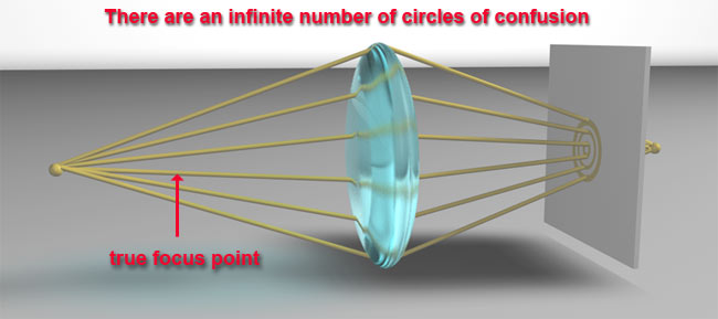
The yellow point represents a point beyond the focal point, and the diagram shows that the lens will focus it beyond the plane. As its image passes the focal plane, it produces the smaller yellow circle of focus at the focal plane. If either or both of these larger circles are less than the COC (circle of confusion) in size, then they will appear focused (sharp) to the human eye, if not they will be burry. This diagram is not truly to scale and it is much exaggerated to easily show the circles of confusion. In reality, each of the points in the real world will create an infinite number of focal crossing points that are in alignment with the focal plane. Those created near the center of the lens will have smaller COC values, and those that are focused from the outer edges will create larger COC values. All of the COC values will be used in the final image, thus all values above the COC will add to the blur effect. Those below the COC will produce maximum sharpness. |
|||||||||||||||||||||||||
 |
||||||||||||||||||||||||||
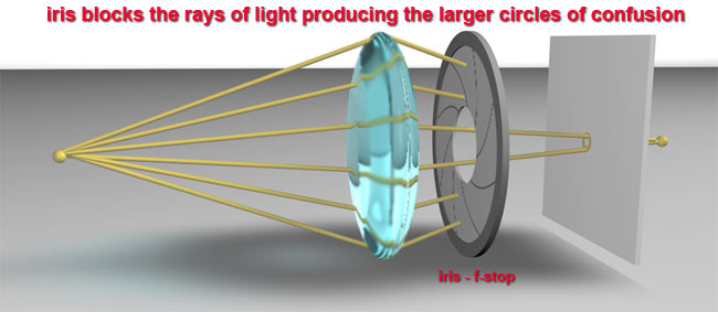
| So what happens when we close down the IRIS (increase the f-stop)? We block the rays on the outer edges of the circle and remove more and more of those rays that add to the blurring of the image. We let pass those rays that are nearer the image axis and produce smaller COC values. (See image below.) | ||||||||||||||||||||||||||
 |
||||||||||||||||||||||||||
| There is a secondary problem with the IRIS. The smaller the IRIS opening, and the more "out of round" the IRIS is, the more it will contribute to stronger light diffraction. IRIS mechanisms tend to be made up of 6 or 8 bladed mechanisms that approximate a true circle, but are in fact flat parallel surfaces. Diffraction is light bending that occurs when passing through a slit or when light passes from medium to another.
Light moving through a slit will be diffracted once the slit is small enough, and the smaller the slit the more the diffraction. The bending causes multiple wave trains on the exit side of he slit, some become additive and others become subtractive. The additive ones produce reinforcement which produces concentric rings of enhanced light on the focal plane. This creates the equivalent of larger circles of confusion that might otherwise (in a non diffracted world) have been created. Thus too small of an aperture will effectively reduce sharpness due to the diffraction limit. For further information and reading try this site cambridgeincolour.com. (Look at the site for other excellent tutorials too.) |
||||||||||||||||||||||||||